This is an old revision of the document!
Enginuity SGM-125-2 Tracking Generator Module
The SGM-125-2 is a prototype dual-channel Signal Generator built around an Arduino Nano board and the relatively common AD9833-MCP41010 0 -- 12.5MHz signal generator module, and it implements its rather limited 'tracking generator' functionality via a broadband RF detector and an ADS1015 multi-channel ADC module.
It was designed to be used within a minimal Automatic Test Equipment mainframe, and uses one of my parser libraries to implement an SCPI-like command interface.
Specifications
| Channels | 2 |
|---|---|
| Functions | Sine, Triangle, Square |
| Frequency Range | 0 -- 12.5 MHz |
| Output Voltage Range | 0 -- 5V via the BNC connectors, 0 -- 15V via the MIC4452 gate drivers (square wave only) |
| Output Coupling Modes | DC, AC |
| Detector Voltage Range | 0 -- 5V (clamped) |
| Unit ID Address Range | 0 -- 7 |
| Interfaces | SCPI-Lite CLI via a Multi-Master TTL UART bus or the built-in CH340 USB UART interface |

Supported Commands
This section summarises the SCPI-like commands supported by the SGM-125-2 Tracking Generator Module. Note that, with the exception of the *TRG command, a module will only respond to a command if its address (as determined by Address ID jumpers) matches the mainframe's current active ID.
The following symbols are used throughout the rest of this section to represent the different type of possible numeric arguments:
| Symbol | Meaning |
|---|---|
<NR1> | Signed integer value |
<NR2> | Floating point value without an exponent |
General Commands
| Syntax | Description |
|---|---|
++ADDR <NR1>++ADDR? | Specifies the address of the module which should now become active. <NR1> is an integer value in the range from 0 to 7. Note that the module's ID is determined by its address select jumpers during initialisation. An address of 7 corresponds to no jumpers and, as such, should be reserved for standalone use (i.e. when not in a mainframe). Its query form, ++ADDR?, is an alias for *IDN?. |
*IDN? | Query only: Returns the modules identification code using an IEEE 488.2-like notation. |
*RCL | Restores the module's settings from the copy stored in non-volatile memory. (The settings are stored using the *SAV command.) |
*RST | Restores the module's settings to its 'factory default' values. |
*SAV | Stores the module's settings into non-volatile memory. You can later use the *RCL command to restore this saved state. |
*TRG | Equivalent to TRIGger:IMMediate, however this form will be processed by all modules in a mainframe, not just the active one. |
HELP? | Query only: Returns a high-level summary of the module's command set. |
SYStem:ADDRess? | Query only: Returns the module's address (assuming it is the currently active unit). |
Module-specific Commands
| Syntax | Description |
|---|---|
OUTput<X> { 0 | 1 }OUTput<X>? | Sets or queries the state of the specified channel's output. OFF and DISable are valid aliases for 0, as are ON and ENable for 1. Can also be invoked using its long-form OUTput<X>:STATe command equivalent. |
OUTput<X>:COUPling { AC | DC }OUTput<X>:COUPling? | Sets or queries the coupling mode for the specified channel. The default is DC. |
SOURce<X>:AMPlitude <NR2>SOURce<X>:AMPlitude? | Sets or queries the output amplitude for the specified channel. <NR2> is a dimensionless number with a range of 0 through 1. This command doesn't have any effect when outputing a square waveform. |
SOURce<X>:FUNCtion { SINe | TRIangle | SQUare }SOURce<X>:FUNCtion? | Sets or queries output function or waveform for the specified channel. |
SOURce<X>:FREQuency <NR2>SOURce<X>:FREQuency? | Sets or queries the output frequency for the specified channel. <NR2> is the desired frequency in Hertz. |
SOURce<X>:FREQuency:STARt <NR2>SOURce<X>:FREQuency:STARt? | Sets or queries the starting sweep frequency for the specified channel. <NR2> is the desired frequency in Hertz. |
SOURce<X>:FREQuency:STOP <NR2>SOURce<X>:FREQuency:STOP? | Sets or queries the ending sweep frequency for the specified channel. <NR2> is the desired frequency in Hertz. |
SOURce<X>:PHASe <NR2>SOURce<X>:PHASe? | Sets or queries the phase offset for the specified channel. <NR2> is the desired phase in degrees; this value will be rounded to the nearest supported offset, given the AD9833's more granular phase control. |
SOURce<X>:SWEEP:MODE { MANual | AUTo }SOURce<X>:SWEEP:MODE? | Sets or queries the sweep mode for the specified channel. |
SOURce<X>:SWEEP:NSTEP <NR1>SOURce<X>:SWEEP:NSTEP? | Sets or queries the number of frequency steps to be used during a sweep for the specified channel. |
SOURce<X>:SWEEP:FSTEP <NR2>SOURce<X>:SWEEP:FSTEP? | Sets or queries the frequency step size to be used during a sweep for the specified channel. |
SOURce<X>:SWEEP:DWELL <NR2>SOURce<X>:SWEEP:DWELL? | Sets or queries the dwell time (or the time between frequency steps) to be used during a sweep for the specified channel. |
TRIGger:IMMediate | Triggers the module (assuming it is the currently active unit). |
TRIGger:SOURce { EXTernal | TIMer }TRIGger:SOURce? | |
TRIGger:TIMer <NR2>TRIGger:TIMer? | Sets or queries the time delay between when the module is triggered and when the frequency sweep should start. |
DETector<X>? | Query only: |
Gallery
 | 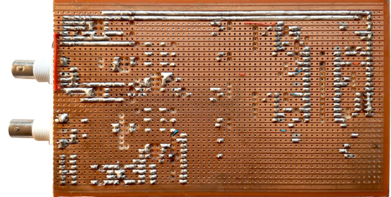 | 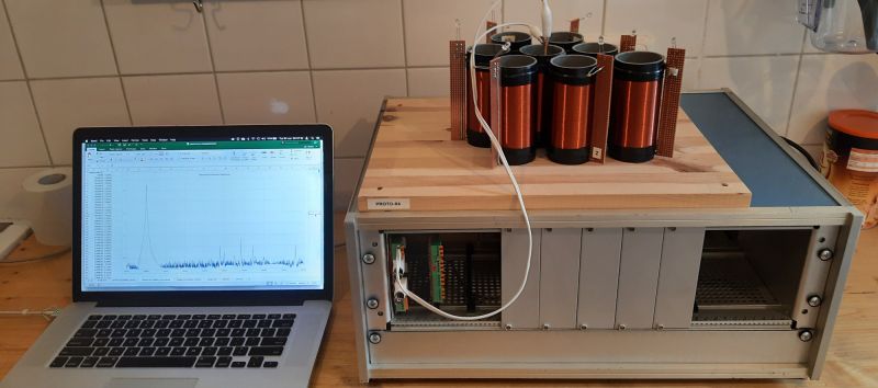 | 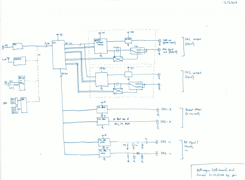 | 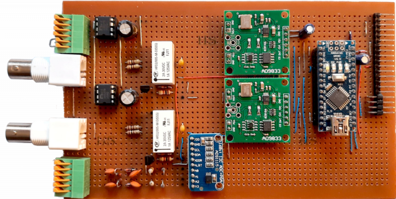 |
Resources and References
- Category:
- ATE, Signal Generator
- Entry:
- SGM-125-2 Tracking Generator ATE Module
- Make:
- Enginuity
- Model:
- SGM-125-2
- Description:
- Custom dual-channel 12.5MHz Signal Generator module with limited tracking functionality and an SCPI-like command interface
- Status:
- Working prototype
- Release-year:
- 2020