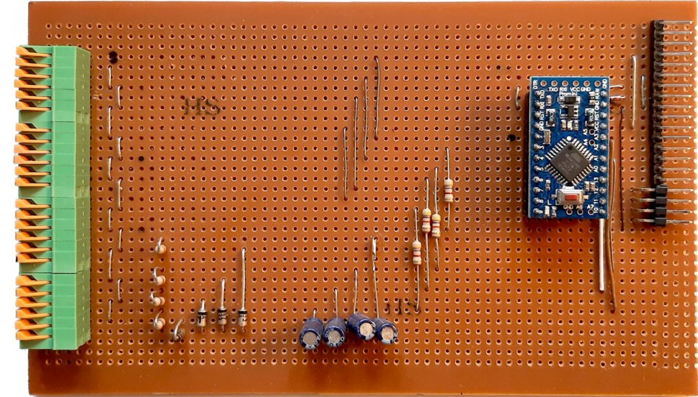
Enginuity IOM-8-4 Basic I/O Module
The IOM-8-4 is a (very) simple prototype multi-channel I/O module with support for 8 digital and 4 analogue I/O lines. It was designed to be used within a minimal Automatic Test Equipment mainframe, and uses one of my parser libraries to implement an SCPI-like command interface.
Specifications
Also add precisions here.
| I/O Channels | 8 Digital, 4 Analogue |
|---|---|
| Output Voltage Range | 0 -- 5V |
| Analogue Input Voltage Range | 0 -- 5V (clamped) |
| Unit ID Address Range | 0 -- 7 |
| Interfaces | SCPI-Lite CLI via a Multi-Master TTL UART bus or the built-in CH340 USB UART interface |
Supported Commands
This section summarises the SCPI-like commands supported by the IOM-8-4 Basic I/O Module. Note that, with the exception of the *TRG command, a module will only respond to a command if its address (as determined by Address ID jumpers) matches the mainframe's current active ID.
The following symbols are used throughout the rest of this section to represent the different type of possible numeric arguments:
| Symbol | Meaning |
|---|---|
<NR1> | Signed integer value |
<NR2> | Floating point value without an exponent |
General Commands
| Syntax | Description |
|---|---|
++ADDR <NR1>++ADDR? | Specifies the address of the module which should now become active. <NR1> is an integer value in the range from 0 to 7. Note that the module's ID is determined by its address select jumpers during initialisation. An address of 7 corresponds to no jumpers and, as such, should be reserved for standalone use (i.e. when not in a mainframe). Its query form, ++ADDR?, is an alias for *IDN?. |
*IDN? | Query only: Returns the modules identification code using an IEEE 488.2-like notation. |
*RCL | Restores the module's settings from the copy stored in non-volatile memory. (The settings are stored using the *SAV command.) |
*RST | Restores the module's settings to its 'factory default' values. |
*SAV | Stores the module's settings into non-volatile memory. You can later use the *RCL command to restore this saved state. |
*TRG | Equivalent to SYStem:TRIGger, however this form will be processed by all modules in a mainframe, not just the active one. |
HELP? | Query only: Returns a high-level summary of the module's command set. |
SYStem:ADDRess? | Query only: Returns the module's address (assuming it is the currently active unit). |
Module-specific Commands
| Syntax | Description |
|---|---|
AIO<X> <NR2>AIO<X>? | Sets or queries the value of the specified analogue I/O channel, where <NR2> (or the value returned by a query) is a floating point number in the range 0 through 1. |
AIO<X>:MODE { INPUT | OUTPUT }AIO<X>:MODE? | Sets or queries the mode of the specified analogue I/O channel. |
DIO<X> { 0 | 1 }DIO<X>? | Sets or queries the state of the specified digital I/O channel. If its corresponding mode is OUTPUT, setting a 0 results in a 0V output, while a 1 results in a 5V output. If it is in an input mode, setting the state to 0 is also equivalent to changing its mode to INPUT, while setting it to 1 is the equivalent to changing its mode to INPUT_PULLUP |
DIO<X>:MODE { INPUT | INPUT_PULLUP | OUTPUT }DIO<X>:MODE? | Sets or queries the mode of the specified digital I/O channel. |
SYSTem:TRIGger | Currently unimplemented: In future versions of the firmware, this would cause the values of any output channels to reflect their most recently set values if SYSTem:TRIGger:MODE is LATCHED. |
SYSTem:TRIGger:MODE { LATCHED | IMMediate }SYSTem:TRIGger:MODE? | Currently unimplemented: In future versions of the firmware, LATCHED mode would allow the output channels' values to be set sequentially but 'written' in parallel upon receiving a trigger signal. |
Gallery
Resources and References
- Category:
- ATE, I/O
- Entry:
- IOM-8-4 Basic I/O ATE Module
- Make:
- Enginuity
- Model:
- IOM-8-4
- Description:
- Custom simple, multi-channel digital and analogue I/O module with an SCPI-like command interface
- Status:
- Working prototype
- Release-year:
- 2020


